Accessing OTSLM from LabVIEW
It is possible to use functionality from OTSLM in LabVIEW. This can be useful for implementing user interfaces which can be easily customised or for integrating OTSLM with existing code.
To run MATLAB scripts from LabVIEW, you will need to use
MathScript
or Interface for
MATLAB depending
on the version of LabVIEW you are using. We have provided an example
package using LabVIEW NXG 3.1 (using LabVIEW Interface for MATLAB) in
the examples/labview folder of the toolbox.
This section provides an overview of the LabVIEW example package and the PrismsAndLenses example LabVIEW application. The example package only provides the features needed for the PrismsAndLenese example. We welcome contributions from LabVIEW users to improve this package to provide better coverage of the OTSLM functionality.
Contents
Creating an otslm.simple function interface
LabVIEW Interface for MATLAB (LIFM) provides a system for defining different interfaces to matlab functions. Using LIFM, you can specify the input parameter names and types in order to create an object that can be imported into a VI. The current version of LabVIEW Interface for MATLAB doesn’t provide a good method for dealing directly with string constants or named parameters, instead it is better to create a separate VI which wraps the LIFM interface.
In this section we take you through defining a interface for the
otslm.simple.lienar() function. This function takes two required
inputs (the size of the pattern and spacing of the grating) and outputs
a 2D array of doubles for the pattern. The complete example can be found
in
otslm/examples/labview/OtslmMatlabInterface/otslm.gcomp/simple/linear.mli
and
otslm/examples/labview/OtslmMatlabInterface/otslm.gcomp/simple/linear.gvi.
Start by creating a new Interface for Matlab, go to: File > New
> Interface for MATLAB. In the box marked Select a MATLAB program
file or enter a MATLAB function name enter otslm.simple.linear and
click Add interface node. Click Add parameter five times and
name the parameters im, sz, spacing, centre_str and
centre as shown in Fig. 26.
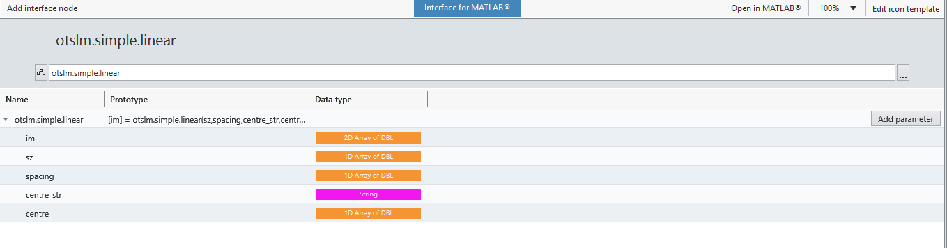
Fig. 26 Setting up the parameters for the Matlab interface
to otslm.simple.linear().
To change the data types and the input/output mode for the parameters, click on the parameter and change the corresponding settings in the Item panel, as shown in Fig. 27.
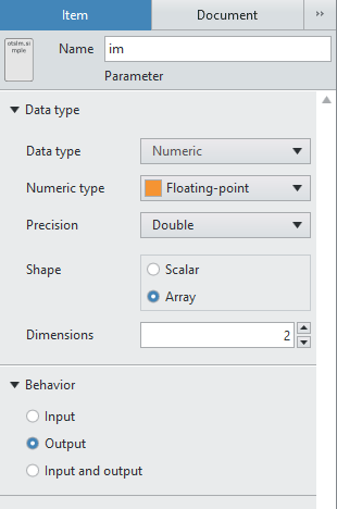
Fig. 27 Screenshot of the item configuration panel.
In order to use this interface the OTSLM path must be added to the
Matlab path. You can do this either by adding the OTSLM path in the
Startup.m script, as described on the getting started page, or you
can run a script which adds OTSLM to the Matlab path. In the example
package, we run a script to add OTSLM to the path. The initOtslm.m
script, located in the examples/labview directory contains the
following code:
function initOtslm()

  fname = mfilename('fullpath');
  [fpath, ~, ~] = fileparts(fname);
  fparts = split(fpath, filesep);

  % Add current path
  addpath(fpath);

  % Add toolbox path
  toolbox_path = fullfile(fparts{1:end-2});
  addpath(toolbox_path);

end
The script first finds the path for the mfile, adds the
examples/labview directory to the path and adds the relative path
for the otslm directory to the path. To call this script, you will
need to create another Matlab interface and specify the file path to
this script. The interface for this script doesn’t need any parameters.
This script should be run at the start of each LabVIEW session or at the
start of each LabVIEW application.
The Matlab interface created for otslm.simple.linear() can now be
included in LabVIEW applications or VIs. To use the interface, you must
connect values to each of the input and output parameters and optionally
the input/output error connectors. However, most of the time you will
not need to change all of the parameters, for instance, the
centre_str parameter will always be the string 'centre'. To
simplify the interface and allow customisation of the icon we can create
a wrapper VI for the Matlab interface. To create a new VI, click
File > New > VI. Add the Matlab Interface VI you just
created to the centre of the diagram and connect nodes to the terminals
as shown in Fig. 28.
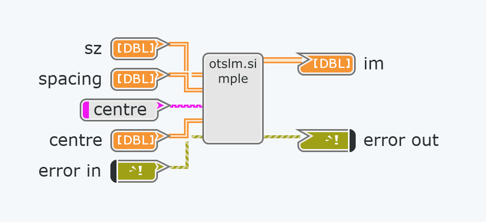
Fig. 28 Wrapper for LabVIEW interface for matlab.
This interface can be further improved, for instance, making the centre
array optional and checking the length of the array is correct. For
example code, see linear.gvi.
Once the diagram has been configured, you can create a front panel to test the interface and configure the icon.
Calling a function with a cell array
The otslm.tools.combine() function takes as input a cell array of
patterns to combine and returns a single pattern as the result. LabVIEW
doesn’t currently provide a mechanism for calling a function with a cell
array, however we can work around this by writing a wrapper function
which takes a 3D array of images and converts them to a cell array of 2D
images. The unpackCombine.m function in examples/labview does
exactly this:
function varargout = unpackCombine(input3, varargin)

  input = mat2cell(input3, size(input3, 1), size(input3, 2), ...
    ones(1, size(input3, 3)));

  input = squeeze(input);

  [varargout{1:nargout}] = otslm.tools.combine(input, varargin{:});

end
It is now possible to create an LabVIEW Interface for Matlab using this function as described in the previous section.
Creating an otslm class interface
In order to use OTSLM classes, such as otslm.utils.ScreenDevice
we need to construct and instance of the object, call its methods and clean
up the instance once we are done. LabVIEW only supports creating
function and script interfaces for Matlab. In order to work around this,
we can write a dispatch method which creates the class instance and
handles calls to the function methods. The following is an example of a
dispatch method:
function varargout = callClassMethod(varname, classname, methodname, varargin)

assert(~isempty(varname), 'varname must be supplied');

tmpvarname = 'ourargs';

if isempty(methodname) && ~isempty(classname)

  % Create a new instance of the class
  assignin('base', tmpvarname, varargin);
  evalin('base', [varname, ' = ', classname, '(', tmpvarname, '{:});']);

elseif isempty(classname) && ~isempty(methodname)

  % Call a class method
  assignin('base', tmpvarname, varargin);
  [varargout{1:nargout}] = evalin('base', [varname, '.', methodname, '(', tmpvarname, '{:});']);

else
  error('Only classname or methodname must be supplied');

end
This function places the Matlab class instance in the base workspace, we
keep track of the class instance using a string (varname) in
LabVIEW. To use this dispatch method, we need to create a LabVIEW
Interface for MATLAB for the class and add each class method we wish to
use, including the constructor and destructor. For
ScreenDevice, the interface might look
something like the one shown in Fig. 29.
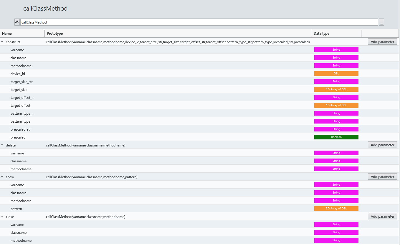
Fig. 29 An interface example for a Matlab class using the
callClassMethod dispatch function.
We can then implement a wrapper VI for each of these methods as
described in the previous sections. The classname and methodname
arguments specify the constructor name and the class method name to be
called. For the destructor, use the string 'delete' for the method
name. In order to use this interface, we need to keep track of the class
instance name and make sure we construct and delete the object before
using other methods of the class. For example usage, see
Building an application.
Building an application
This section describes building a LabVIEW application for generating a
Prisms and Lenses hologram which is drawn using
ScreenDevice.
You can find the finished application in
examples/labview/OtslmMatlabInterface/PrismsAndLenses.gcomp. This
example assumes you have followed the above instructions to implement
your own VIs for the spherical, linear, combine and
ScreenDevice OTSLM functions/classes or you are using the examples
provided in the examples/labview/OtslmMatlabInterface/otslm.gcomp
package. If you use the example application/package, you will need to
modify the path in otslm.gcomp/initOtslm.mli to find the correct
path for the initOtslm.m file.
Create a new application in LabVIEW by going to File > New > Application. Name the application. Add a new VI to the application for the front panel (where the main user interface will be displayed): right click on the application icon in the project browser and click: New > VI, as shown in Fig. 30.
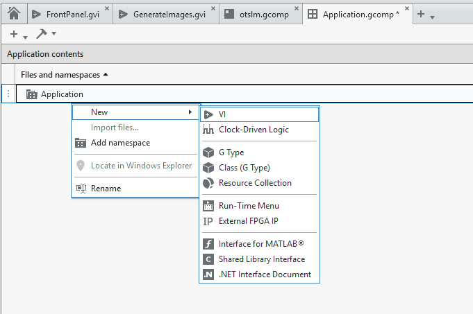
Fig. 30 Adding a new VI to an application.
Create the VI by adding the controls shown in Fig. 31.
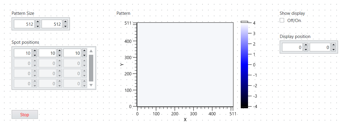
Fig. 31 Layout of front panel.
The user interface will allow the user to specify the size and position of the window on the screen, change the number and location of spots in the Prisms and Lenses algorithm, and see a preview of what the image will look like on the screen.
To implement this, we need to initialise OTSLM, construct the screen
device object for displaying the patterns, generate the array of
patterns to pass to otslm.tools.combine for each spot the user requests,
and display the result in the previous and on the screen.
To generate the array of patterns for each prisms and lenses spot, we will create a sub-vi which takes as input the pattern size and spot locations and generates a 3D array of patterns which we can pass to combine. Add a new vi to your application and configure it with the nodes shown in Fig. 32.
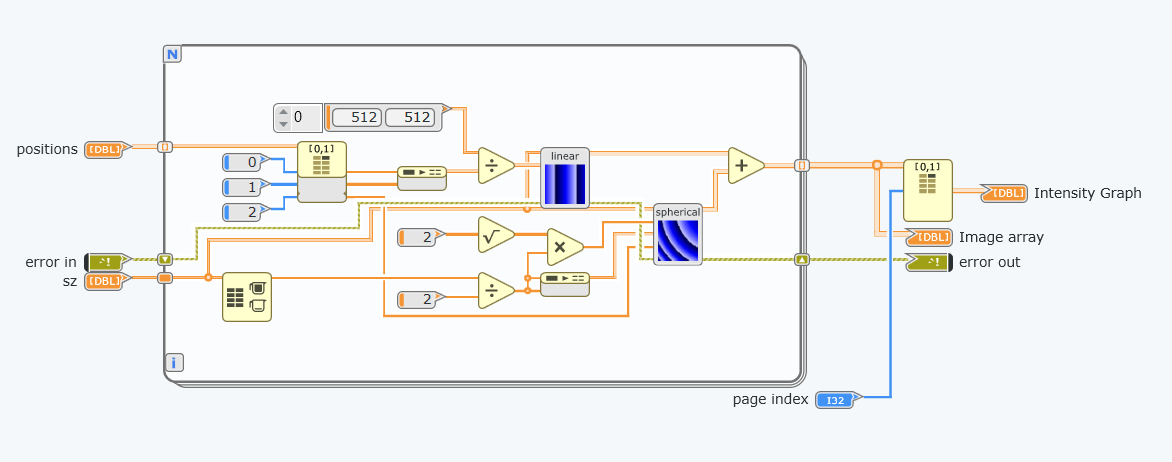
Fig. 32 Layout of generate images diagram.
To add the spherical and lenses sub-vis, either click and drag the VIs from the project file tree or add them from the Project Items menu, as shown in Fig. 33.
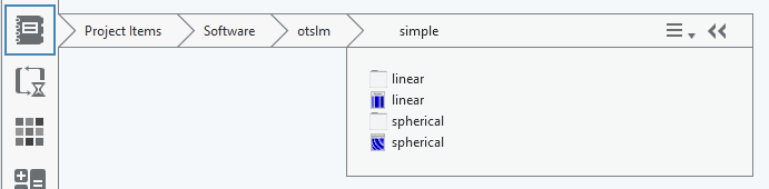
Fig. 33 Using the project items menu.
Connect the input and output nodes in the icon diagram as shown in Fig. 34.
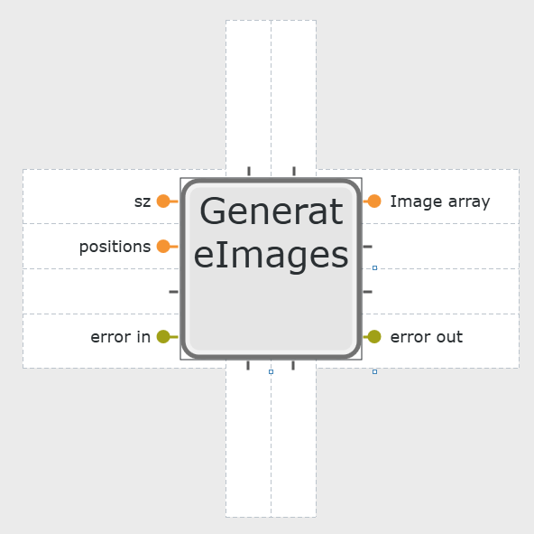
Fig. 34 Layout of generate images icon.
Next, switch back to the front panel diagram and construct the program shown in Fig. 35.
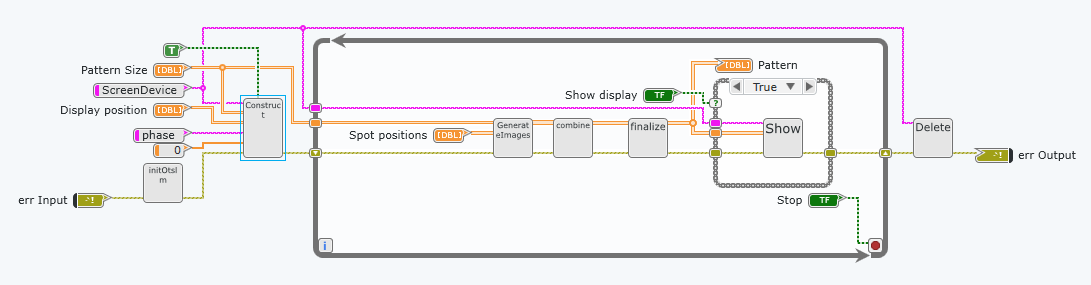
Fig. 35 Layout of the front panel diagram.
In this example we use a loop to continuously update the display when
the user changes inputs to the VI. The ScreenDevice is positioned and
constructed outside the loop, this means that the size of the pattern
and location are fixed throughout the entire run of the program. If the
show display checkbox is not clicked, the ScreenDevice is asked to
close, otherwise the pattern is displayed to the screen.